SpiderGraph
System Design

Marc Cohen
Patrick DeMoss
Yevgen Voronenko
Frederick Walsh
Leland Weeks

Mar 12, 2003

 
spider_graph_logo.jpg
Available online at http://www.mcs.drexel.edu/uyvorone/cs452/

Contents

1  Introduction
    1.1  Abstract
    1.2  Purpose
    1.3  Document Scope
    1.4  Design Goals
    1.5  Definitions, Acronyms and Abbreviations
    1.6  Overview of the Remainder of the Document
2  General Architecture
    2.1  Implementation Plan
    2.2  Environment Components
    2.3  Architecture
    2.4  Use cases
3  Graph Display
    3.1  XUL Design
    3.2  graphDisplay file structure
        3.2.1  Content
        3.2.2  Skin
        3.2.3  Locale
    3.3  graphDisplay.xul
        3.3.1  MenuBar
        3.3.2  Buttons
        3.3.3  Display Area
    3.4  graphDisplay.js
        3.4.1  openGraph()
        3.4.2  saveGraph()
        3.4.3  saveAsGraph()
        3.4.4  close()
        3.4.5  getSelectedNodes()
        3.4.6  prune()
        3.4.7  newRoot()
        3.4.8  cluster()
        3.4.9  updateGraph()
    3.5  graphDisplay.css
    3.6  graphDisplay.txt
    3.7  Summary
4  Data Processing
    4.1  Overview
    4.2  Events
        4.2.1  Overview
        4.2.2  Preferences change
        4.2.3  Browser input
        4.2.4  Graph display interaction
    4.3  Classes
        4.3.1  Edge
        4.3.2  Node
        4.3.3  ConnectedComponent
        4.3.4  Graph
5  Browser UI
    5.1  Overview
    5.2  SpiderGraph Button
        5.2.1  Visual
        5.2.2  Implementation
    5.3  Data Collection
6  Preferences
    6.1  Overview
    6.2  Changeable Parameters
        6.2.1  Fonts
        6.2.2  Themes
        6.2.3  Clustering/Color coding options
        6.2.4  Enable/Disable SpiderGraph
        6.2.5  Uninstall function
        6.2.6  About Button
7  Delivery and Installation
    7.1  Delivery Strategy
    7.2  XPInstall
    7.3  Considerations for Machine Dependent Code
8  GraphViz / DOT
    8.1  Description
    8.2  Sample DOT Input
    8.3  DOT Attributes
9  Mozilla
    9.1  Overview
    9.2  Mozilla in Relation to SpiderGraph
A  Index
B  Section Authors
C  Bibliography
Index

List of Figures

    1  Implementation plan timeline
    2  Top level data-flow diagram
    3  Use-case diagram
    4  graphDisplay file structure
    5  Sample GraphDisplay window
    8  All the present Modern navigation buttons
    10  Interaction between XUL and other MOZILLA and SpiderGraph components
    11  Current navigation interface
    6  graphDisplay file contents and dependencies
    7  Graph data processing classes
    9  MOZILLA browser with the close-up of SpiderGraph button
    12  Preferences dialog
    13  XPInstall dialog
    14  Sample DOT input
    15  Sample DOT output
    16  Controllable node attributes in DOT
    17  Controllable edge attributes in DOT
    18  Controllable graph/subgraph attributes in DOT

1   Introduction

1.1  Abstract

The most commonly used navigation tools in modern web browsers are the Forward and Back navigation buttons. However, in many cases the default implementations of these buttons are unsatisfactory for the user.
SpiderGraph is intended to improve the standard navigation buttons by storing user click history in a graph data structure, and then displaying the history graph on demand to allow easy navigation to all previously visited pages. It will also offer the user the option of decorating the graph with other information, helping the user to quickly locate the desired location.
The SpiderGraph design proposed in this document will provide a specification for software implementation.

1.2  Purpose

SpiderGraph Requirements Specification [5] described the core functionality of the SpiderGraph web browser extension.
This document is intended to delineate system architecture and design of the SpiderGraph system web browser extension. It illustrates structural and functional design issues; describes system dependencies, collaboration and composition relations, and inheritance hierarchy.
It will serve as a basis for implementation of the first SpiderGraph release - SG-1 .

1.3  Document Scope

This document provides a complete design of the SpiderGraph package, and specifies how the functional and non-functional requirements set in [5] will be satisfied.
Complete software architecture is presented, and subpackages, classes, and functions are described. Also user-interface prototypes are given.
Note, this document does not describe a working system, and thus might contain certain assumptions, which might be proven to be wrong in the implementation phase.

1.4  Design Goals

The ultimate goal of this design document is to build an interactive history graph extension for the MOZILLA web browser, that uses the existing graphing tool, but improves its graph layout capabilities by using domain specific information about web pages.
Target design shall possess the following characteristics:
Perhaps the most useful subset of SpiderGraph would be the graph production and data transformation parts, which can be reused for the creation of other types of related graphs - such as web server statistics or directory and filesystem hierarchies.

1.5  Definitions, Acronyms and Abbreviations

clickpath
The order in which a set of web pages or nodes are traversed.
cluster
A set of related nodes grouped together or consolidated into a single node.
domain
A group of web pages that belong to the same address or domain name.
edge
A directional or non-directional line which shows the relationships between two nodes.
graph
A diagram that exhibits a functional relationship between a set of elements.
GraphViz
A graph layout and rendering package.
GUI
Graphical User Interface
hypertext
Computer based text retrieval system that enables a user to access particular locations in web pages or other electronic documents by clicking on links.
link
A reference from some point in a hypertext document to some point in another document or another place in the same document.
Mozilla
Web browser application.
navigate
To traverse through the world wide web.
node
A point or vertex in a graph.
prune
To remove unnecessary or unwanted nodes and edges in a graph.
render
Process of visualizing internal representation of graphical objects.
root
The starting point or the first node of a graph.
RPM
Red Hat Package Manager
SeaMonkey
Codename for the current MOZILLA browser.
transitive
The relation x to y and the relation y to z implies the relation x to z.
tree
A graph in which there is only one route between any pair of nodes.
UI
User-interface, in most cases refers to GUI
URL
Uniform Resource Locator
W3C
World Wide Web Consortium http://www.w3.org/
web browser
An application used to navigate the world wide web.
web server
A process running at a web site which sends out web pages in response to HTTP requests from remote browsers.
weight
The varying degree of importance of an edge.
XPCOM
Cross-Platform scheme for turning objects into discrete components.
XPConnect
Binding between XPCOM and JavaScript.

1.6  Overview of the Remainder of the Document

The rest of this documents presents the overall SpiderGraph architecture, implementation and testing plan, and detailed component designs.
Sections 8 and 9 can be consulted for information regarding GRAPHVIZ and MOZILLA respectively.

2   General Architecture

2.1  Implementation Plan

First release of SpiderGraph, known as SP1, will be completed by the end of May. The main development will start as soon as the first proof-of-concept prototype will be "hacked" together. It will proceed through three milestones:
Figure 1 shows absolute deadlines for SpiderGraph milestones. All of the shown deadlines represent the latest possible date the subtask must be finished by.
plan.png
Figure 1: Implementation plan timeline
Alpha and beta milestones will be followed by rigorous testing. The aim of alpha and beta testing is to reveal possible problems in the implementation. Alpha and beta testing will be performed by SpiderGraph team.
End-user testing is aimed at finding possible problems with the user interface, such as inconsistencies in naming or GUI layout. To find volunteers1 for end-user testing, an announcement will be made in class, and also on the project web site.

2.2  Environment Components

SpiderGraph is not a stand-alone application. It is a browser extension and it coexists in a software environment consisting of the following meta-components:
SpiderGraph will be implemented as an add-on for the MOZILLA web browser. It will add a new button to the navigator and also have its own window. Final stages of graph production will utilize DOT, a graph layout and rendering engine, which is part of GRAPHVIZ package.

2.3  Architecture

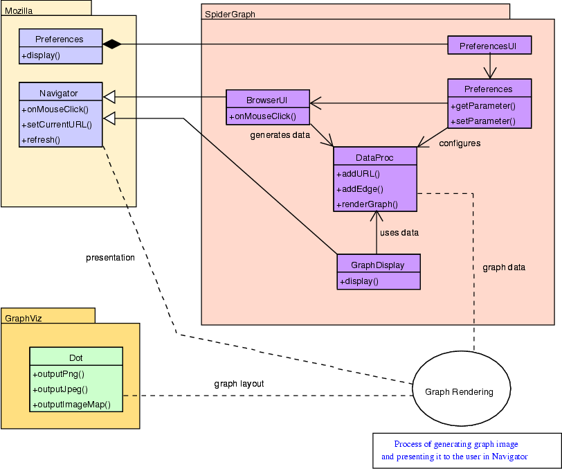
Internally SpiderGraph will be organized into 4 subpackages:
Diagram 2 shows how these components interact with each other.
TopLevelDataflow.png
Figure 2: Top level data-flow diagram

2.4  Use cases

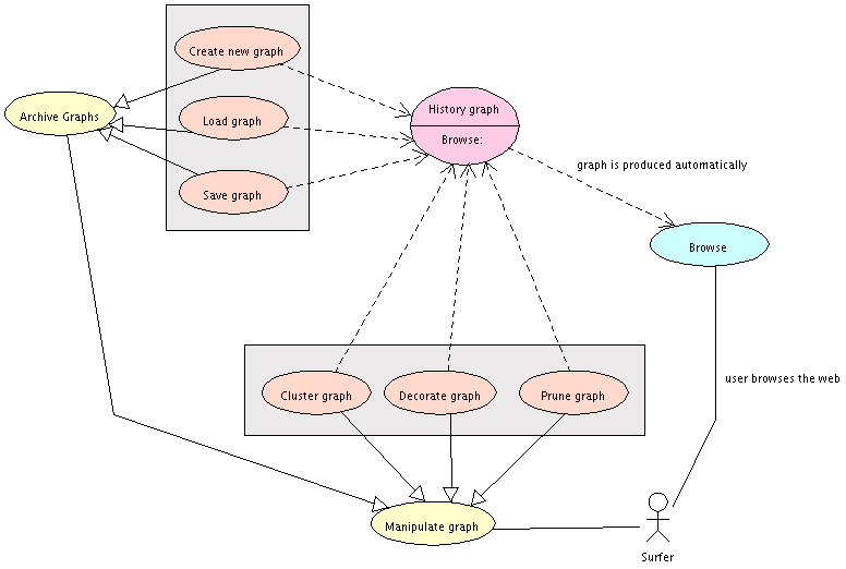
UseCase.png
Figure 3: Use-case diagram

3   Graph Display

3.1  XUL Design

The graphs generated by SpiderGraph will be displayed in a standalone window within the MOZILLA application. However, because the current MOZILLA web browser does not provide a suitable window for this purpose, it will be necessary to incorporate a new type of window into the web browser.
In order to maintain consistency within the design of the MOZILLA web browser, the layout and event handling for the new window will be written in XUL format. As such, the design of the window that SpiderGraph will use to display its graphs will adhere to standard XUL guidelines. More specifically, the design of the window will be broken down into the three standard XUL components, content, skin, and locale.

3.2  graphDisplay file structure

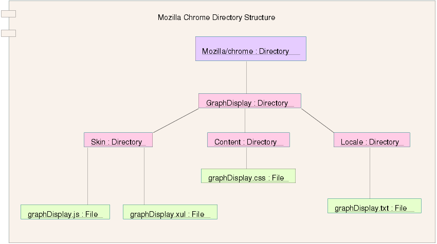
Together, the XUL design of the window will be incorporated into the MOZILLA web browser as a package named graphDisplay. That is, it will be placed inside the chrome directory located inside of the MOZILLA folder on the machine in which MOZILLA is installed. The overall file structure of the window design and incorporation into the MOZILLA directory structure is shown in the Figure 4.
dirs.png
Figure 4: graphDisplay file structure

3.2.1  Content

As is customary in XUL design, the content portion of the new window will contain information that is relevant to the layout and actions of the window. For example, the placement, size and shape of any buttons, in addition to their actions, will be housed in this portion of the window design. There will be two files that are created in order to do this. The first will be the XUL file that contains the declaration and layout of all objects within the window. This file will be written in XUL and named graphDisplay.xul. The second file will be named graphDisplay.js and will be written in JavaScript. It will contain the code that is executed when the user performs an appropriate action within the graph display window (ie clicks on a button).

3.2.2  Skin

The skin portion of the window will contain all of the material responsible for the appearance of the window. More specifically, this portion of the window design will include any cascading style sheets and images, other than the graph, that are utilized by the window. The style sheet information will be stored in a file called graphDisplay.css.

3.2.3  Locale

Finally, the locale portion of the code will contain any text that is to be displayed outside of objects such as buttons or windows. More specifically, anytime text that is unrelated to the buttons or images is to be inserted in the window, it will be stored in a separate file and housed in the locale directory of the graph display window. This file will be named graphDisplay.txt.

3.3  graphDisplay.xul

This file will contain all of the layout information necessary to generate the window the users browsing history graph will be presented in. It will consist of a menubar, numerous buttons, and a graph display area.

3.3.1  MenuBar

The menubar will consist of only one entity, a File menu. However, there will be a total of four options under the File menu.

3.3.2  Buttons

The window in which the users browsing history graph is displayed in will contain a total of three different buttons. They will reside in horizontal fashion along the top of the window just below the menubar. The three buttons will be named as follows:

3.3.3  Display Area

This portion of the window will contain the space in which the graph is actually presented. It will be presented in the middle of the window and be specified as an iframe object within graphDisplay.xul.
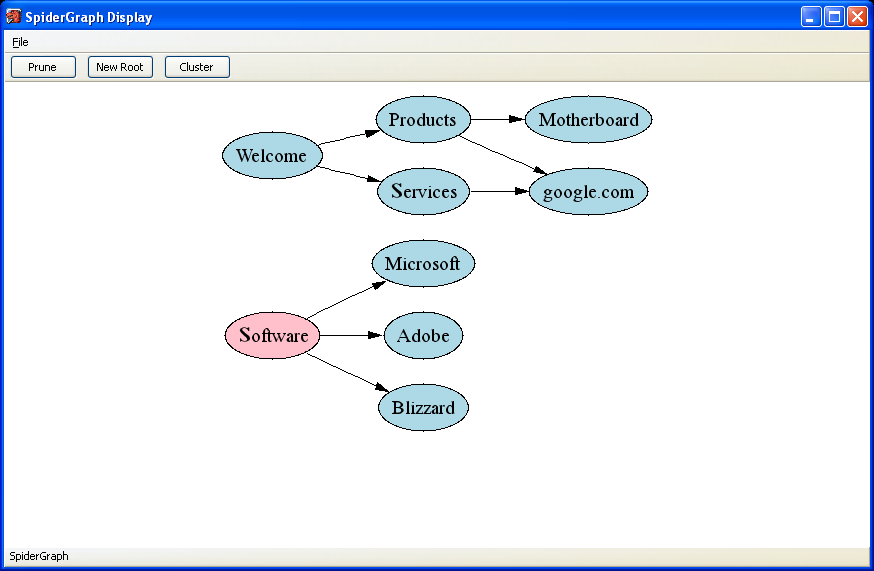
Figure 5 shows a sample display window.
displayGraph_screenShot.png
Figure 5: Sample GraphDisplay window

3.4  graphDisplay.js

This file will contain all of the code that is executed when a menu item, button, or node within the active graph is selected. It will also contain the functions that allow communication between the display window and the processing component of SpiderGraph. All of the functions will be written in JavaScript.
Note: There is no function which tells the browser to point to a particular website when a node in the graph is clicked on because the graph is represented as an imagemap. As such, the data contained within the imagemap handles this aspect of functionality.
The complete list of functions in addition to their inputs and outputs follows below.

3.4.1  openGraph()

3.4.2  saveGraph()

3.4.3  saveAsGraph()

3.4.4  close()

3.4.5  getSelectedNodes()

3.4.6  prune()

3.4.7  newRoot()

3.4.8  cluster()

3.4.9  updateGraph()

3.5  graphDisplay.css

This file will contain all the specifications necessary to give the window the graph is displayed in the desired look and feel. It will be written in cascading style sheet format. Because the window is an expansion package to MOZILLA, the look and feel of the window shall match that of the standard MOZILLA interface.

3.6  graphDisplay.txt

This file will contain all of the textual information that is displayed in the window other than the text presented in the menubar, buttons, and nodes of the graph. Because the requirements of the system does not call for any additional text to be presented in the window, this file will be left blank and simply reside in its location to keep with the specification of XUL. Should it be deemed necessary to add any additional text to the window, it will be placed in this file.

3.7  Summary

The following diagram summarizes the files and their associated content:
summary_of_files.png
Figure 6: graphDisplay file contents and dependencies

4   Data Processing

4.1  Overview

The graph data will be held in a single data structure so as to facilitate manipulation and archival operations. All data needed to generate the browsing history graph is stored here, including node and edge properties.
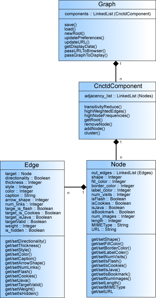
The data structure will be implemented in JavaScript following an object-oriented design. Several objects comprise the primary Graph object:
Figure 7 shows UML class relationship diagram for this module.
class-diagram3.png
Figure 7: Graph data processing classes

4.2  Events

4.2.1  Overview

The data structure's major functionality exists to handle three specific events:
  1. Preference change.

  2. Browser input.

  3. Display interaction (includes button activation and interaction with the graph).

4.2.2  Preferences change

This event occurs when the user makes any changes to the set preferences held in the MOZILLA SpiderGraph menu option. Initially these preferences will be set to default values, but as the user makes changes to these values, the graph must update itself accordingly as soon as the changes are confirmed. The preference information is held in the UI component of the MOZILLA browser and is implemented in JavaScript.
event1.txt.png
The PrefsListener object will serve as an event listener, and pass all preference parameters to the Graph data structure once the user has made a change. The data structure will update itself according to the new user choices, and then pass this information on to the Graphviz utility for the new graph to be generated.

4.2.3  Browser input

Any input from the browser which changes the current URL will trigger this event. Such user actions as a bookmark selection or a manual URL entry qualify as a Browser Input event. Data will be passed to the Graph data structure using the BrowserListener object, which retrieves the new URL from the MOZILLA browser.
event2.txt.png
The new URL will be recorded in the Graph data structure appropriately, and then the new data will be passed to the Graphviz utility so that the displayed graph can be updated.

4.2.4  Graph display interaction

This event occurs when the user interacts with any part of the graph display, such as activating nodes or buttons. The DisplayListener object listens to the display module for any user interaction, and when it is triggered it passes the information to the Graph data structure.
event3.txt.png
If the graph is altered, the data structure must update itself to correspond to the changes in the displayed graph. If a new URL is requested by the user using the displayed graph, then the Graph data structure must update itself appropriately, by incrementing that site's visit count for example, and then finally passing that new URL to the browser to visit.

4.3  Classes

4.3.1  Edge

Identification EDGE
PurposeThe edge object represents a single edge in the graph, or a link from one website to another. It will hold a single pointer to a Node object to represent the node toward which it is pointing (not from). Also, all user preference information is stored in the object, such as arrow shape and thickness. Site tracking data such as link count (weight) and a variable to remember if the target site is special (Flash/Cookies/Java), are stored here as well.
FunctionThis object realizes the following functional requirements:
  • 3.3.1: Directionality

  • 3.3.3: Edge Style

  • 3.3.4: Edge Derived Style

  • 3.3.5: Deriving Style for weighted edges

Dependencies NODE
Aside from expected edge attributes, this object carries a pointer to the Node object. This pointer represents a node which is pointed to by this edge.
MethodsStandard functions
Edge exists as one of two objectes which complete what is essentially an adjacency list representation of a graph. Aside from the usual inspector and modifier methods, there are no special functions to consider.
DataInternal data of this object will consist of a list of nodes, as well as various attributes which are used optionally by the user to give information about the edge.
  • LinkedList <Node>

  • directionality

  • thickness

  • style

  • color

  • caption

  • arrow shape

  • visit count

  • weight

  • visible

4.3.2  Node

Identification NODE
PurposeThe Node object represents a single node in the graph, or a single website. It will hold a list of Edges to represent all edges pointing from this node and toward another, as well as all user preference parameters such as color and shape. Various site tracking data is also stored here, such as the visit count, site length, and URL.
FunctionThis object realizes the following functional requirements:
  • 3.2.1: Node Labels

  • 3.2.2: Node Style

  • 3.2.3: Node Derived Style

  • 3.2.4: Uniqueness

  • 4.2.3: Inspecting nodes

  • 4.3: Preferences

Dependencies EDGE
Aside from the expected node attributes used to define user preferences, this object holds a vector of Edge objectes. All edges which exist in this Node instance are graphically represented as edges leaving this node. The nodes to which these edges point are defined in the Edge object.
MethodsStandard functions
The Node object complements the Edge object in the goal of representing a complete graph as an adjacency list. In addition to the corresponding inspector and modifier methods, each Edge from the vector of Edges is accessible using LinkedList methods.
DataInternal data of this object is made up of a list of Edges, as well as basic optional node properties definable by the user:
  • LinkedList <Edge>

  • shape

  • fill color

  • border color

  • label color

  • visit count

  • image count

  • length

  • MIMEType

  • URL

4.3.3  ConnectedComponent

Identification CNCTDCOMPONENT
PurposeA connected component is simply a graph which includes no isolated nodes or subgraphs, that is, if the graph were undirected, any node in the graph would be accessible from every other node. This is our single graph representation, implemented as a list of Node objectes, or an adjacency list. For each start node, or root as defined in the requirements document, a single connected component exists. All browsing patterns originating from the root will automatically cause the connected component to grow, as the object adds nodes (corresponding to new websites) to itself.
FunctionThis object realizes the following functional requirements:
  • 3.5.1: Growth direction

  • 3.5.2: New nodes

  • 3.5.3: Stability

  • 3.6: Pruning

  • 3.7.1: Partial Equivalence Clustering

  • 3.7.2: Grouping clustering

  • 3.7.3: Reduction clustering

  • 4.2.3: Inspecting nodes

  • 4.2.4: Adding New Edges and Nodes

  • 4.2.5: Inspecting the graph

  • 4.3: Preferences

Dependencies NODE
The graph data is held in a list of Nodes.
MethodsRetrieval and assignment to a specific node or edge within the graph is accomplished using appropriate methods from the LinkedList and internal methods from the Node or Edge objectes.
transitivityReduce()
This method exists to keep the graph cleaner and less complex. It reduces the graph in accordance with the transitivity relationship; that is, given an edge a->b and an edge b->c, we can eliminate the edge a->c since it is already implied.
highWeightedEdges()
This method will find the x highest-weighted edges in the connected component and highlight them in a color designated by the user. This weight currently represents link count (number of times used).
highNodeFrequency()
This method highlights x nodes with the highest visit count in a color which is previously defined by the user.
getRoot()
Returns the Node which exists at the front or 0th index position of the vector. This place is reserved for the root or start node.
removeNode()
Nodes in the connected component are deleted entirely using this method. All edges leaving this deleted node, and all nodes and edges derived thereafter are also deleted. This method is meant to support manual as well as automatic deletion of nodes (pruning) in accordance with the Preference design.
addNode()
A node and corresponding edge will be added to connected component. This would usually be done automatically, as the user were to browse websites and add to the browse history. The growth of the graph happens with the use of this method.
cluster()
Related nodes are grouped together according to domain or another criterium using this method. Proper use of this method can greatly reduce the size of the graph, as a cluster of nodes takes up a very small space relative to the nodes it contains or represents. This method is meant to be used for both automatic and manual clustering.
DataInternal data of this object is comprised of a list of Nodes.
  • LinkedList <Node>

4.3.4  Graph

Identification GRAPH
PurposeThis is the primary object which holds all graph information. All individual connected components (each with a single root) are stored here as a single graph. Data in this object would be passed to the Graphviz utility for the generation of the actual graph display.
FunctionThis object enables events 1, 2, and 3 as defined in this section: Preference Change, Browser Input, and Display Interaction.
This object realizes the following functional requirements:
  • 3.4.3: Multiple roots

  • 3.4.4: Automatically getting new roots

  • 3.4.5: Manually creating new roots

  • 4.2.6: Changing the Root

  • 4.3: Preferences

Dependencies CNCTDCOMPONENT
This object holds all CNCTDCOMPONENT instances in a list.
Methods CNCTDCOMPONENT instances and all other specific data are accessed using linked list methods, as well as internal methods within the CNCTDCOMPONENT, NODE, and EDGE objectes.
setRoot()
This method creates a new Connected Component, comprised only of a single start node or root.
save()
To store the current graph data for the next browser session, or to archive the data for future use, this method can be used to write the current browser history graph to the drive.
load()
This method is used to load a previously saved browser history graph into the data structure, thus making the loaded data the current graph.
updatePreferences()
This method is used to tell the data structure that new preferences have been defined, and that the data needs to be updated with the new settings.
updateURL()
When a new URL is entered from the browser, this method is used to update the current URL to the one entered. The data structure will then generate a new graph and pass it to the display.
getDisplayData()
When the user interacts with the displayed graph, this method is used to retrieve specific data about the interaction, such as command code (Prune, Open Graph..., etc.) and any data needed for the operation.
passGraphToDisplay()
This method generates a stream or file which can be used by GraphViz to generate a graphical browser history graph, complete with interactive nodes. It then sends a message to the Display to refresh its current graph with the newly generated one.
passURLToBrowser()
When the user chooses to visit a site by activating a node in the displayed graph, the corresponding URL of the node is passed to the MOZILLA browser to visit using this method.
DataInternal data of this object is a vector of CNCTDCOMPONENT instances.
  • LinkedList <CnctdComponent>

5   Browser UI

5.1  Overview

MOZILLA's Graphical User Interface language is XUL, or Extensible User-Interface Language. It is a cross-platform language for describing user interfaces of applications and is modeled after XML, Extensible Modeling Language. Since MOZILLA is required to run on several platforms, the user-interface has several technical specifications and requirements.
MOZILLA's UI is divided into three layers: structure, style, and behavior. The structure layer identifies the widgets (menus, buttons, etc.) and their position in the UI relative to each other, the style layer defines how the widgets look (size, color, style, etc.) and their overall position (alignment), and the behavior layer specifies how the widgets behave and how users can use them to accomplish their goals.

5.2  SpiderGraph Button

5.2.1  Visual

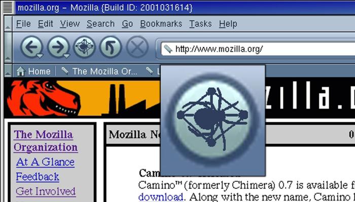
A single button will be added to the current MOZILLA user-interface for the implementation for SpiderGraph. Two different themes or skins of the SpiderGraph button will be created.
Four different versions of a button must be created for each skin. Therefore, several images of the above SpiderGraph buttons must be made:
navigation_buttons.png
Figure 8: All the present Modern navigation buttons
The two skins are called "Classic" and "Modern". The new SpiderGraph buttons for each theme are shown in Figure 9.
classic_browser_insert.jpg
Classic Theme
modern_browser_insert.jpg
Modern Theme
Figure 9: MOZILLA browser with the close-up of SpiderGraph button

5.2.2  Implementation

A XUL file describes the elements of the user-interface and where each element will appear. Therefore, modifications to the XUL file will be required to add the button to the user-interface. The XUL language defines attributes that allow the programmer to define where the elements appear and actions and controls related to the element. Specifically, a JavaScript function will be called each time the SpiderGraph button is clicked. The JavaScript will open the SpiderGraph window. Since the window is simply another MOZILLA browser window, the coding for the interaction with the button will be straightforward.
uml.jpg
Figure 10: Interaction between XUL and other MOZILLA and SpiderGraph components
The main MOZILLA navigation interface, shown in Figure 11, is found in the chrome directory. The chrome directory is the main repository for the menu, navigation buttons, and any customizable user interface components.
navigation.png
Figure 11: Current navigation interface
XUL makes use of tags to create user-interface elements. Here is a simple example of XUL code that will add a button to the MOZILLA web browser:
<button
    id="SpiderGraph"
    label="SpiderGraph"
    image="images/SGmodern.jpg"
    default="false"
    disabled="false"/>
It will be necessary to write interaction for the SpiderGraph button. The button may have an event handler with code that looks similar to the following:
<?xml version="1.0"?>
<?xml-stylesheet href="chrome://global/skin/" type="text/css"?>
<window
    id="mozilla-window"
    title="Mozilla"
    orient="horizontal"
    xmlns:html="file://spidergraph.html"
    xmlns="file://spidergraph.html ">
Finally, by design, XUL has been created with install packages in mind. Therefore, our modifications will be able to be packaged into an installer, which the user may download and install.
The functionality and requirements of the button can be traced back to section 4.1, SpiderGraph Button, of the requirements document.

5.3  Data Collection

The MOZILLA browser needs to send all visited links to SpiderGraph for processing. The two ways MOZILLA can obtain a new link is from the user clicking on a link, typing a URL, or selecting a bookmark.
The NETLIB II URL collection of classes contains more than just the ASCII string that the W3C standard calls a URL, as it contains all the data associated with a URL operation: the address, the host's IP addresses, the method, the content-type, etc. Basically, it's the old URL_Struct, cleaned up and rewritten. This class must be modified to send the string to SpiderGraph.
Additionally, it is important to note that MOZILLA is unique in that it implements a hierarchy of string classes. Strings are often created for particular functions and therefore each particular type of string has it's own class definition. For instance, different string classes exist for ASCII, RTF-8, read-only strings, concatenation, etc.
The functionality and requirements of the button can be traced back to section 1.3, Goals, of the requirements document.

6   Preferences

6.1  Overview

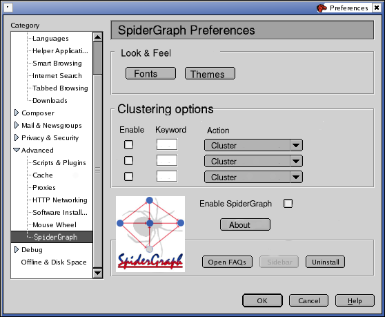
Preferences will contain all user changeable variables in SpiderGraph. It shall be accessible from the preference dialogue in MOZILLA. The data shall be stored in an object with attributes via get and set methods. Figure ?? shows a screenshot of Prefences dialog.
Screenshot-prefs.png
Figure 12: Preferences dialog

6.2  Changeable Parameters

6.2.1  Fonts

Fonts will be handled by a standard font dialogue provided by the operating system. The only font necessary to be configured will be the font used for the graphs.

6.2.2  Themes

Themes and Skins can be installed to change the overall look and feel of SpiderGraph. They are set via a standard file dialogue provided by the operating system.

6.2.3  Clustering/Color coding options

This option gives the functionality to cluster or color code the nodes together based upon a keyword. High contrast color schemes for accessibility will also be offered here. This option will be presented as a string input box followed by a list of colors/actions in a combo box. The user will enter the keyword of their choice in the String box and choose the appropriate action via the combo box.

6.2.4  Enable/Disable SpiderGraph

This option enables/disables SpiderGraph. When this option is disabled, the SpiderGraph button is reverted back to the forward button.

6.2.5  Uninstall function

This options allows the user to uninstall SpiderGraph, It is not so much an option, but script that removes the software.

6.2.6  About Button

The about button is also not an option, when clicked it brings up a dialog crediting SpiderGraph?s contributors and displays version data.

7   Delivery and Installation

7.1  Delivery Strategy

SpiderGraph aims to be distributed on as many platforms as possible and have the easiest installation as possible. SpiderGraph will supply the following packages:
SystemPackage typePackage name
win32install executableInstall Shield Setup.exe
debianaptspidergraph_VERSION.deb
redhatrpmspidergraph_VERSION.rpm
Mac OS Xdmgspidergraph_VERSION.dmg
UnixSourcespidergraph_VERSION.tar.gz
Since we are porting SpiderGraph to so many architectures, the packaging process will be automated, we employ MAKE and use cross-compilers to do this for us.

7.2  XPInstall

XPInstall, or "XPI", is a file format used by MOZILLA for plug-ins it shall be embraced as much as possible as it adds much needed functionality and usability. XPI is essentially a compressed archive that contains a small JavaScript program that registers modules within MOZILLA. Although it does have some shortcomings as it lacks the ability to install machine specific portions. Figure 13 shows a screenshot of XPInstall installer dialog.
Screenshot--installation.png
Figure 13: XPInstall dialog

7.3  Considerations for Machine Dependent Code

Certain portions of SpiderGraph must be machine specifically compiled, i.e. GraphView libraries. These portions will be kept in a directory of the users choice queried during installation.
The install will be automated but it will contain two parts.
  1. Modifying current data: This will consist of editing the "chrome.xml" so that SpiderGraph will be added to the user interface of MOZILLA, and other file the needs to by changed to allow for SpiderGraph. On the win32 this will be a simple batch script and on the Debian, Redhat, Unix and to a lesser extent Mac OS X it will be a simple shell script.

  2. Copying Data: This consist of copying all of the xul, binaries and other data to the local hard disk so that it can be accessed.

8   GraphViz / DOT

8.1  Description

SpiderGraph relies heavily on dot, one of several components belonging to Graphiz, an open source graph-drawing utility program offered by AT&T. The overall process of SpiderGraph can best be described on a high level as follows. Initially, SpiderGraph extracts information from MOZILLA about a user's browsing history. The data processing unit than parses the information it receives from MOZILLA and organizes it in such a fashion as to allow dot to draw a graph representing the data. Dot than creates and returns an imagemap based upon the information that is spoon-fed to it. The resulting imagemap is than displayed back to the user via a specialized window in the MOZILLA web browser. As such, in order to fully understand the design of SpiderGraph, an elementary understanding of dot and some of its features is necessary.
Essentially what dot does is draw either directed or undirected graphs. As with all graphs, this requires that a set of vertices in addition to the edges between them be specified. In terms of SpiderGraph, all graphs will be directed. In addition, the vertices will represent web pages and the edges between them will represent the path taken by the user in order to view the pages.

8.2  Sample DOT Input

What follows is an example of a file that SpiderGraph may generate and pass along to dot. Its purpose is to introduce the syntax of the dot language.
NOTE: the double slash, //, represents a comment in the dot code and as such it is utilized here to explain what each line of code is doing in the file.
digraph G {   // begin graph declaration
   rankdir = LR;            //draw graph from left to right
   labelloc = "center";     //name of node will appear in the center
 
   //change the style node to pink with black border
   node [style = filled, fillcolor = "pink", color = "black"]; 
   
   //create node called Software
   Software      
   
   //change the style node to pink with black border
   node [style = filled, fillcolor = "lightblue", color = "black"];
 
   Software -> Microsoft; // A->B mean an edge is drawn from A to B
   Software -> Adobe;
   Software -> Blizzard;
 
   edge[style = bold];  //make edge thicker
   Welcome -> Products; //note this starts a new root because no edges
                       //exist between the nodes below and above
   Welcome -> Services;
   Products -> Motherboard;
   Products -> "google.com";
   Services -> "google.com";
}
Figure 14: Sample DOT input
graph.png
Figure 15: Sample DOT output
Although not all of the features available in dot and utilized by SpiderGraph have been utilized in this example, the general format and use of all features offered by dot and utilized by SpiderGraph have been demonstrated. For example, in the above code, if we wanted to add a URL to the node represented by "Software", the following statement would simply be inserted into the node declaration in the preceding line:
node [style = filled, fillcolor = "pink", 
      color = "black", URL = "http://www.xyz.com"];

8.3  DOT Attributes

DOT file has a graph (and possibly subgraphs), nodes, and edges. Each of these objects has controllable attributes. These attributes control the layout and appearance of the graph.
DOT attributes are summarized in the following three tables:
dot1.png
Figure 16: Controllable node attributes in DOT
dot2.png
Figure 17: Controllable edge attributes in DOT
dot3.png
Figure 18: Controllable graph/subgraph attributes in DOT

9   Mozilla

9.1  Overview


l]0.10mozilla_logo.png
MOZILLA is an open source web browser first created in March of 1998 when Netscape released their portion of copyrighted code for the Netscape Navigator browsers and components to the open source community. However, Netscape could not release all of the source code for the browser so a community named mozilla.org was created to rewrite the missing portions of code, creating the first open source web browser. Since then, MOZILLA has been one of the largest ongoing projects in the open source community.
MOZILLA consists of several subcomponents. Components that need to be taken into consideration with the implementation of SpiderGraph include: SeaMonkey, User Interface, Help Viewer, JavaScript, Netscape Portable Runtime, Plug-ins, Necko/Gecko, XPCOM, and XPConnect.

9.2  Mozilla in Relation to SpiderGraph

SpiderGraph is plug-in for MOZILLA which allows for increased functionality in the navigation of webpages. When a user visits a new URL, it will be sent to the SpiderGraph navigational window, which is just a specialized MOZILLA window. SpiderGraph will use the data collected from the user and DOT to generate an image map in the specialized navigational window.

A  Index

B  Section Authors

C  Bibliography

References

[1]
AT&T Research Labs , "The DOT Language", http://www.research.att.com/erg/graphviz/info/lang.html, February 2003.
[2]
AT&T Research Labs , "Welcome to GraphViz", http://graphviz.org/, February 2003.
[3]
Andersen, A., Deakin, N., "XUL Planet", http://www.xulplanet.com/, March 2003.
[4]
Bergmann, S., "phpOpenTracker", http://www.phpopentracker.de/, February 2003.
[5]
Cohen, M., et al. "SpiderGraph Requirements Specification", http://www.mcs.drexel.edu/uyvorone/cs452, February 25, 2003.
[6]
Institute of Electrical and Electronics Engineers, "Hyperlinks", RFC 1866, Institute of Electrical and Electronic Engineers, 1998.
[7]
Jupitermedia Corporation, "JavaScript Source", http://javascript.internet.com/, March 2003.
[8]
Kendall, S., "Unified Modeling Language Dictionary", http://www.softdocwiz.com/UML.htm, March 2003.
[9]
Mozilla Organization, The, "Mozilla Hackers's Getting Started Guide", http://www.mozilla.org/hacking/coding-introduction", Febuary 2003
[10]
Mozilla Organization, The, "Mozilla Navigator Source Code", http://ftp.mozilla.org/pub/mozilla/releases/mozilla1.3b/src/mozilla-source-1.3b.tar.gz, March 2003
[11]
Mozilla Organization, The, "Tutorial: Creating a Mozilla Extension", http://www.mozilla.org/docs/tutorials/tinderstatus, March 2003
[12]
Rational Software, "UML Resource Center", http://www.rational.com/uml/, March 2003.

Footnotes:

1It is not possible for the SpiderGraph team to perform this step, since we designed the UI, we would conclude it is the best.


File translated from TEX by TTH, version 3.33.
On 12 Mar 2003, 15:22.