SpiderGraph
Software Requirements Specification Revised

Marc Cohen
Patrick DeMoss
Yevgen Voronenko
Frederick Walsh
Leland Weeks

Jun 2, 2003

 
Available online at http://www.mcs.drexel.edu/uyvorone/cs452/

Contents

1  Introduction
    1.1  Abstract
    1.2  Purpose of this document
    1.3  Goals
    1.4  Scope of the product
    1.5  Definitions, acronyms and abbreviations
    1.6  Overview of the remainder of the document
2  General Description
    2.1  Product perspective
    2.2  Product functions
    2.3  User characteristics
    2.4  General constraints
    2.5  Assumptions and dependencies
3  Graph Rendering and Formatting Requirements
    3.1  Description
        3.1.1  Graph description
        3.1.2  Graph rendering
    3.2  Nodes
        3.2.1  Style
        3.2.2  Uniqueness
    3.3  Edges
        3.3.1  Directionality
        3.3.2  Derived Style
        3.3.3  Deriving style for weighted edges
    3.4  Root
        3.4.1  Definition
        3.4.2  Initialization
    3.5  Growth
        3.5.1  Growth direction and scrolling
        3.5.2  New nodes
        3.5.3  Stability
    3.6  Pruning
4  User Interaction Requirements
    4.1  SpiderGraph Button
    4.2  Graph Interaction
        4.2.1  Visiting nodes
        4.2.2  Adding New Edges And Nodes
5  Non-Functional Requirements
    5.1  Product
    5.2  Installation
    5.3  Development
    5.4  External requirements
6  Requirements for Next Development Phase
    6.1  Nodes
        6.1.1  Labels
        6.1.2  Style
        6.1.3  Derived Style
    6.2  Edges
        6.2.1  Transitivity
        6.2.2  Style
        6.2.3  Derived Style
    6.3  Roots
        6.3.1  Multiple roots
        6.3.2  Automatically getting new roots
        6.3.3  Manually creating new roots
    6.4  Clusters
        6.4.1  Partial equivalence
        6.4.2  Grouping clustering
        6.4.3  Reduction clustering
    6.5  User Interaction Requirements
        6.5.1  Inspecting nodes
        6.5.2  Selecting nodes
        6.5.3  Inspecting the graph
        6.5.4  Changing The Root
7  System Evolution
    7.1  Overview
    7.2  External documentation
        7.2.1  Major design decisions
        7.2.2  Evolutionary changes
    7.3  Internal documentation
    7.4  Changes and their impact
    7.5  Programming languages
    7.6  Past versions
    7.7  Extensibility
        7.7.1  Extensible design
        7.7.2  Future work
A  Index
B  Screenshots
C  Bibliography
Index

List of Figures

    1  Typical browser behavior compared to SpiderGraph enhancement
    2  phpOpenTracker server clickpath graph
    3  Static hypertext link graph for a hypothetical web site
    4  Redundancy based graph reduction
    5  Unstable versus stable graph layout
    6  Complete URLs as labels in a history graph
    7  Derived styles in a history graph
    8  Grouping clustering of highly connected node sets
    9  Reduction clustering for nodes on the same domain
    10  Sample design decision documentation entry
    11  Sample evolutionary change log entry
    12  Prototype system screenshot 1
    13  Prototype system screenshot 2

1  Introduction

1.1  Abstract

The most commonly used navigation tools in modern web browsers are the Forward and Back navigation buttons. However, in many cases the default implementations of these buttons are unsatisfactory for the user.
The figure below shows a typical situation: a user visits search engine A, clicks on a link to B, clicks Back, and then visits C. Thus reference to B is lost, and there is no way to get quickly back to B without clicking the actual link again.
Figure 1: Typical browser behavior compared to SpiderGraph enhancement
SpiderGraph is intended to improve the standard navigation buttons by storing user click history in a graph data structure, and then displaying the history graph on demand to allow easy navigation to all previously visited pages. SpiderGraph will also offer the user the option of decorating the graph with other information, helping the user to quickly locate the desired location.

1.2  Purpose of this document

This document serves to specify the complete functional and non-functional requirements for the SpiderGraph project. It illustrates the various system features and functional details for the end-users and SpiderGraph developers.

1.3  Goals

SpiderGraph is intended to produce an easy-to-use Mozilla web browser extension that generates and renders the URL history graph. The extension will allow the user to easily locate and navigate to previously visited URLs.
The following components will be produced:
  1. History graph formatter - generates the history graph with user-specified parameters, and computes all relevant decorations

  2. History graph renderer - displays the generated graph in a window

  3. Mozilla GUI for the renderer - provides for user interaction with a graph

1.4  Scope of the product

SpiderGraph will provide a fully working interactive history graph extension for Mozilla web browser. It will use the existing graphing tool, and will improve its graph layout capabilities by using domain specific information about web pages.
SpiderGraph is not intended to provide a full graphing capability, but will instead be based on an existing graphing package. Core graphing capabilities will be provided by the GraphViz suite.

1.5  Definitions, acronyms and abbreviations

clickpath
The order in which a set of web pages or nodes are traversed.
cluster
A set of related nodes grouped together or consolidated into a single node.
domain
A group of web pages that belong to the same address or domain name.
edge
A directional or non-directional line which shows the relationships between two nodes.
graph
A diagram that exhibits a functional relationship between a set of elements.
GraphViz
A graph layout and rendering package.
GUI
Graphical User Interface
hypertext
Computer based text retrieval system that enables a user to access particular locations in web pages or other electronic documents by clicking on links.
link
A reference from some point in a hypertext document to some point in another document or another place in the same document.
Mozilla
Web browser application.
navigate
To traverse through the world wide web.
node
A point or vertex in a graph.
prune
To remove unnecessary or unwanted nodes and edges in a graph.
render
Process of visualizing internal representation of graphical objects.
root
The starting point or the first node of a graph.
RPM
Red Hat Package Manager
transitive
The relation x to y and the relation y to z implies the relation x to z.
tree
A graph in which there is only one route between any pair of nodes.
URL
Uniform Resource Locator
web browser
An application used to navigate the world wide web.
web server
A process running at a web site which sends out web pages in response to HTTP requests from remote browsers.
weight
The varying degree of importance of an edge.

1.6  Overview of the remainder of the document

The rest of this documents presents functional and non-functional requirements for the SpiderGraph system and the future evolution. Requirements for the initial phase of this product are given in sections three, four, and five. Additionally requirements for future development phases are given in sections six and seven.

2   General Description

2.1  Product perspective

SpiderGraph builds graphs of web page relationships. In the basic operational mode the graph represents the user click history, however the formatter makes it possible to augment the graph with other information derived from the web pages themselves. In general, the formatter might transform the graph by eliminating unnecessary edges, or by reassigning the edges based on some predefined notion of structure.
Producing the simple graphs of web page relationships is not difficult with the tools that exist today. However, even for small web sites the graphs tend to get out of hand, and become very hard to interpret. For example, Figure 2 shows a web server derived clickpath graph, produced by phpOpenTracker. The graph shows weighted paths taken by the users between 10 different URLs. Unfortunately, it conveys almost no useful information due to the incomprehensible structure.
Figure 2: phpOpenTracker server clickpath graph
SpiderGraph aims to produce highly readable graphs, by using the domain-specific information about web pages to improve graph layout.

2.2  Product functions

The SpiderGraph browser interface builds a tree graph, where each node in the tree represents a web-site and each edge in the tree represents a link (directed toward the linked site from the original site), based upon the user's browsing history. Additionally, the graph might be augmented with derived information.
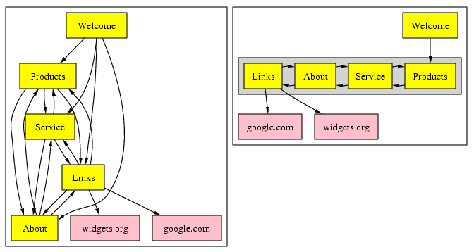
This tree representation enables the user to jump to any desired page in the history, including any pages closely related to the current page that are inaccessible using the conventional Back and Forward browser navigation buttons. Figure 3 shows an example of how such a graph might look like. Note that Products, Services, About, and Links were grouped in a cluster to express their highly connected structure.
Figure 3: Static hypertext link graph for a hypothetical web site
By design, the SpiderGraph interface provides a representation of the user's browsing history. Information that is displayed provides not only the visited pages, but how the user arrived at a particular page. This data could be extremely useful for marketing, tracking, and research purposes1.
The browser history will be represented internally as a graph data structure to which various algorithms can be applied that transform the graph to simplify it, or derive the structural or other properties of a collection of web pages. For example, a user might be interested in seeing just the structure without actually seeing all edges, and thus a graph might be simplified.
Figure 4: Redundancy based graph reduction

2.3  User characteristics

Likely users of SpiderGraph would be those who frequently access the Internet; that is, any current user of a web browser may enjoy and appreciate the graphical representation of site history provided by SpiderGraph. This browser display, which lends a more intuitive and controlled interface, may appeal to a significant number of regular Internet users, hence becoming the preferred browser tool.
The target user community for SpiderGraph would need only an elementary level of computer skill; as with any point-and-click interface.
SpiderGraph will facilitate the use of the web as a research tool, since it will simplify navigation through a large collection of web pages. It would appeal to web designers who wish to visualize their design. Finally, it would be a very useful tool in everyday web browsing.

2.4  General constraints

The web browser application Mozilla, to which SpiderGraph will be added, is open-source and therefore subject to no proprietary or regulatory policies. The same can be said of the display tools within the GraphViz package. SpiderGraph's capabilities are limited only by Mozilla's capabilities, simply because the SpiderGraph project's function is to process data within Mozilla in a specific way, but not necessarily to extend Mozilla's functionality.

2.5  Assumptions and dependencies

The browser to which SpiderGraph will be added is Mozilla, an open-source application that can be used on Windows, Unix, and Macintosh machines. Given the limited time and resources of development for this project, it may not be possible for SpiderGraph to function on all of these platforms, though this is certainly a goal.

3   Graph Rendering and Formatting Requirements

3.1  Description

3.1.1  Graph description

The graph will be generated using the user's browsing history. Each node in the tree will represent a unique URL, and each edge in the tree represents a hypertext link between URLs. Note that possible SpiderGraph extensions might use other meanings for edges.

3.1.2  Graph rendering

InputSites visited through the Mozilla browser.
Processing Build up an internal data structure
Decorate nodes (See section 6.1.3)
Decorate edges (See Section 6.2.3)
Render the graph using GraphViz tools.
OutputDisplayed graph representing browser history.

3.2  Nodes

3.2.1  Style

Node caption and color constitute the node's style. The following factors constitute the node style and will be:
  1. Shape (ex. circle, square, trapezoid, etc.)

  2. Fill color (color of the filled area inside node)

  3. Border color (color of the node boundary)

  4. Label color (color of the text inside node)

Each node will be drawn as a filled circle with a black border. Figure 6 shows a history graph with nodes of oval shape, light blue fill color, transparent border color, and black label color.
InputThe style of the nodes.
ProcessingGraph is rendered using style parameters.
OutputProper node labels are displayed. See the figure below for a complete URL labels example.

3.2.2  Uniqueness

Nodes and graphed URLs have a 1-to-1 correspondence, e.g. for every node, there exists a unique URL which it represents. All URLs that have been represented by a node somewhere in a graph before will not be represented again as a new node in this graph. This means that if the user enters a URL or chooses a Bookmark a new root will not be created, if the node for that URL already exists.
InputA site is visited and automatically contained in a node data structure.
ProcessingIf the current URL exists in a previous node, nothing is done; otherwise, a new node is created as the new root.
OutputNew root or nothing

3.3  Edges

3.3.1  Directionality

Edges will be directed. Directed edges will show the direction of the link with an arrow.
InputHistory graph
ProcessingFormat the edges.
OutputDirected graph layout.

3.3.2   Derived Style

It will be possible to produce graphs with edge styles derived from the web page data. The following characteristics will affect the style derivation for nodes:
  1. Number of visits to a target URL

InputHistory graph.
ProcessingURLs corresponding to nodes are traversed, and their relevant characteristics are derived.
OutputCorresponding edge styles' are updated accordingly.

3.3.3  Deriving style for weighted edges

Each edge will carry a weight property that represents the number of times it has been used. Each time the node v is accessed by linking from node u, the edge weight Wu® v will be incremented.
Each edge that has a high weight relative to other edges will be colored red (or some other noticeable color), so that the user can readily identify this particular edge as one that is often used.
Each node with a high in-degree weight (total weight of edges pointing toward it) relative to other nodes will be colored red (or some other noticeable color), so that the user can readily identify this particular node as one that is often visited.

3.4  Root

3.4.1  Definition

The root of the history graph represents the first site pulled up by the browser window, usually the home page. The root of the history graph will also be known as the start state or start URL.

3.4.2  Initialization

InputBrowser launched, and home page brought up.
ProcessingIf page does not exist in previous tree, tree data structure initialized with page as its root. Graph is drawn.
OutputGraph with a single root node representing the current page.

3.5  Growth

3.5.1  Growth direction and scrolling

The graph will be displayed with a root node in a topmost position, and branches growing down toward the bottom, with scroll capabilities in the graph viewport to enable large tree growth.
InputBrowser history data in tree data structure.
ProcessingAppropriate options will be chosen in the GraphViz tool to produce scrolling.
OutputScrollable viewport.

3.5.2  New nodes

Nodes are added with every traveled link to a new URL, not already in a graph. New URL is represented by a new node connected to the originating page with a directed edge pointing towards the new node.
InputA new page is visited using a link on the current page.
ProcessingA new node representing the new page is created and added to the tree data structure. The display of the old tree is redrawn to reflect the added node.
OutputNew node is added to the graph.

3.5.3  Stability

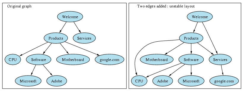
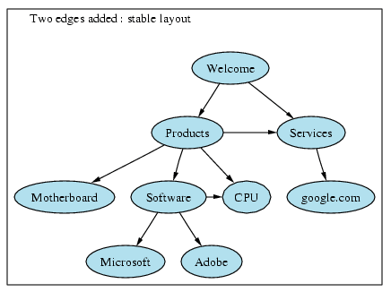
The tree will grow such that the overall shape does not change radically. The user should be able to maintain familiarity with the tree shape and structure. Figure 5 shows an example of uncontrolled graph layout, which violates this rule: when new edges are added, node positioning changes significantly.

Figure 5: Unstable versus stable graph layout
InputContinuous visits to new sites using links will make the tree grow.
ProcessingExisting options chosen within the GraphViz graph-drawing tool will keep the tree stable and familiar as new nodes are added to it. If options do not already exist, algorithms will be implemented towards this purpose.
OutputGraph remains familiar as it grows without radical changes.

3.6  Pruning

Over the course of a browsing session, the history graph keeps growing. To keep it manageable, the number of nodes should not keep increasing, thus at each iteration a graph will be pruned.
Several criteria for removing nodes will be available:
  1. Age - time last visited

  2. Frequency - number of times visited

  3. Relevance - subjective measure based on a position in a tree

InputThe criteria for pruning as such as age or frequency.
ProcessingThe nodes that satisfy the pruning cutoff are removed.
OutputThe graph is redrawn. .

4   User Interaction Requirements

4.1  SpiderGraph Button

A new button for the SpiderGraph will be added to the web browser's interface.
InputThe user will single left-click on the button to open the SpiderGraph window. The user double-clicks on a node in the graph.
ProcessingThe button activates the window.
OutputThe window opens with the current SpiderGraph web page history.

4.2  Graph Interaction

4.2.1  Visiting nodes

Every site already represented in the graph can be immediately accessed by double-clicking on the corresponding node.
InputThe user single-clicks on a node in the graph.
ProcessingSpiderGraph tells Mozilla to open the corresponding web-page. The graph window is deactivated.
OutputMozilla displays the corresponding web-page.

4.2.2  Adding New Edges And Nodes

New nodes are added to the history graph as the user clicks hyperlinks on the web pages.
InputUser click on a link on a web-page.
ProcessingNew node for the target URL is created, if it is not already exists. An edge from node with linking URL to the target is created.
OutputGraph is augmented with a new node and an edge, or an edge to an existing node.

5   Non-Functional Requirements

5.1  Product

  1. SpiderGraph shall execute at a reasonable speed, so as not to interrupt the flow of user interaction.

  2. This software will have negligible overhead over Mozilla.

  3. SpiderGraph will not interfere with the functionality already provided by the web browser.

5.2  Installation

  1. SpiderGraph shall be distributed on Linux and Windows.

  2. The software shall be easily installable, allowing novice users to setup and operate SpiderGraph.

  3. The installation shall only require Mozilla and DOT as a dependency.

  4. SpiderGraph will provide source code and documentation.

  5. All input will be handled by both keyboard and mouse.

  6. SpiderGraph shall provide means so that it can be used for server side navigation.

5.3  Development

  1. This software will be written with source readability as the highest concern.

  2. Portability to other web-browsers shall be a high concern also.

  3. The software shall be licensed with GPL, BSD or similar open-source license.

5.4  External requirements

  1. License and distribution cannot conflict with any of the rules and regulations of Drexel University.

  2. SpiderGraph will be secure and not leak information off the system.

6  Requirements for Next Development Phase

The purpose of this section is to list requirements that were not implemented as originally listed in version 1.8 of this requirements document.

6.1  Nodes

6.1.1  Labels

InputUser input concerning preferences for the labels of the nodes.
ProcessingLabels for the nodes can be a number, added in an incrementing order corresponding to the time-line in which the user visits each page, the domain name of the node, to conserve space, or the entire URL of the web-page. In either case, the space allotted for the node label will be limited and upon selecting the node, the complete label will be displayed.
OutputProper node labels are displayed.
Example Figure 6 shows a graph with URLs as node labels.
Figure 6: Complete URLs as labels in a history graph

6.1.2  Style

Node caption and color constitute the node's style. The following factors constitute the node style and will be user-changeable:
  1. Shape (ex. circle, square, trapezoid, etc.)

  2. Fill color (color of the filled area inside node)

  3. Border color (color of the node boundary)

  4. Label color (color of the text inside node)

Each node will be drawn as a filled circle with a black border. Figure 6 shows a history graph with nodes of oval shape, light blue fill color, transparent border color, and black label color. These parameters will be user changeable via the Preferences facility (Section 6.5.4).
InputUser input concerning preferences for the style of the nodes.
ProcessingGraph is rendered using user specified style parameters.
OutputProper node labels are displayed. See the figure below for a complete URL labels example.

6.1.3   Derived Style

It will be possible to produce graphs with node styles derived from the web page data. The following characteristics will affect the style derivation for nodes:
  1. Number of visits to a URL

  2. Whether the referred page uses Flash / Cookies / Java

  3. Whether a page is in the user's bookmarks

  4. Number of images

  5. Length

  6. MIME type

InputHistory graph. User preference settings for derived style application.
ProcessingURLs corresponding to nodes are traversed, and their relevant characteristics are derived. Individual node style is updated.
OutputCorresponding node styles' are updated accordingly.
Figure 6 with the application of derived style modifiers becomes Figure 7. Here green color shows that google.com is in user's bookmarks, and GraphViz related URL is pink because it is very often visited.
Figure 7: Derived styles in a history graph

6.2  Edges

6.2.1  Transitivity

Edges implied by transitivity are usually redundant, eg. they do not carry useful information for the user, and thus can safely be removed for graph clarity. An example of a simple removal:
{ A® B® C, A® C}Þ{ A® B® C}
In the example above an edge from A to C is removed, since it is implied by a path through B.
InputHistory graph
ProcessingRedundant edges implied by transitive hyperlinking relationship are removed.
OutputReduced history graph.

6.2.2  Style

The following factors constitute the edge style and will be user changeable:
  1. Line thickness

  2. Line style

  3. Line color

  4. Caption

  5. Arrow shape

This first release of SpiderGraph will not assign captions to edges.
Each edge will be drawn as a solid black line with a standard arrow shape. These parameters will be user changeable via the Preferences facility (Section 6.5.4).

6.2.3   Derived Style

It will be possible to produce graphs with edge styles derived from the web page data. The following characteristics will affect the style derivation for nodes:
  1. Whether target URL uses Flash / Cookies / Java

  2. Whether target URL points to a valid page

InputHistory graph.
ProcessingURLs corresponding to nodes are traversed, and their relevant characteristics are derived.
OutputCorresponding edge styles' are updated accordingly.

6.3  Roots

6.3.1  Multiple roots

Multiple roots are allowed on a graph. This implies that several independent browsing sessions were performed with different starting locations.

6.3.2  Automatically getting new roots

Root nodes are automatically created when the user clicks on a URL from his/her Bookmarks, provided that the site not already exists in the graph.
InputA new site is visited without using a link, such as direct URL entry or Bookmark selection.
ProcessingIf the new site does not exist elsewhere in any previously generated graph, then it becomes the root of a new graph. A new data structure is initialized with page as its root.
OutputA new graph is drawn beneath the older graph.

6.3.3  Manually creating new roots

New roots might be selected by the user from existing non-root nodes in order to split the graph. The node will be removed from the original graph and become the root of a new graph, placed just below the last graph.
InputNode is selected and CREATE NEW TREE button is clicked.
ProcessingThe node is removed from its previous tree, along with all nodes in branches extending from it.
OutputOld graph is redrawn and new graph is created and drawn.

6.4  Clusters

6.4.1  Partial equivalence

Partial equivalence relation on nodes is a relation that groups several nodes based on their characteristics. Partial equivalence will be used for graph clustering, and will be determined on a basis chosen by the user. The following list enumerates possible choices:
  1. Same URL - this is the default behavior, nodes with the same URL are always merged, so that the user does not see duplicate URLs in the graph.

  2. Same domain - all nodes on the same domain, for instance drexel.edu.

  3. Same link depth from specific node - all nodes within specific depth of a chosen node.

  4. Highly connected nodes - nodes that form a complete graph.

6.4.2  Grouping clustering

Grouping clustering puts several partially equivalent nodes close together on a graph, removes redundant edges and highlights the region.
InputThe graph. User's criteria for partial equivalence.
ProcessingAll partially equivalent node sets are grouped in a bound area in the layout. Redundant edges implied by transitivity are removed.
OutputThe graph is redrawn with grouped node area is highlighted for easy reference.
Figure 8 shows an example of grouping of several highly connected nodes.
Figure 8: Grouping clustering of highly connected node sets

6.4.3  Reduction clustering

Reduction clustering collapses several partially equivalent nodes into one node. All edges leading into collapsed nodes are redirected into the new node.
InputThe graph. User's criteria for partial equivalence.
ProcessingAll partially equivalent node sets are collapsed into a single node. All edges leading into collapsed nodes are redirected into the new node.
OutputThe graph is redrawn.
Figure 9 shows an example of reduction clustering for a nodes on the same domain.
Figure 9: Reduction clustering for nodes on the same domain

6.5  User Interaction Requirements

6.5.1  Inspecting nodes

The user can retrieve information from the graph by selecting a node, right-clicking on it and then selecting properties.
InputSingle left-click and then right-click.
ProcessingInformation about the node and/or the graph is collected.
OutputThe information is displayed on the screen.

6.5.2  Selecting nodes

A node will become selected by single-clicking on it. Selecting a node enables the user to perform a number of operations (covered later in this section).
InputThe user single-clicks on a node in the graph.
OutputThe selected node is outlined.

6.5.3  Inspecting the graph

Floating the cursor above a node will trigger an unobtrusive text-box to display various information about the node, such as associated URL, related URL that has been visited before (usually the main page), geographical location if possible, etc.
InputThe cursor is floated above a node (no click).
OutputData about the node is displayed in a small text box (like a help box).

6.5.4  Changing The Root

In some cases the user might want to reduce the graph by selecting the new root by hand.
InputUser right-clicks on a node, and selects Make root.
ProcessingSelected node becomes a root. Nodes linking to the root are removed. Graph is reformatted.
OutputGraph is redrawn with a new root.
Preferences
All aspects of the SpiderGraph will be changeable from the Preferences Window.
InputUser selects SpiderGraph Preferences from Mozilla Preferences menu.
ProcessingConfiguration information is collected.
OutputPreferences window is shown with parameters changeable by the user.

7   System Evolution

7.1  Overview

As is expected of all major software systems, SpiderGraph will undoubtedly need to be revised numerous times throughout its lifespan. Reasons for this include but are not limited to errors within the original release, revised or newly formed requirements, and changes in the system's external environment. Unfortunately, it is often the case that changes to a system come at a great cost, financially. This being the case, it is essential that SpiderGraph be designed and maintained in such a fashion that changes to the system can be carried out as efficiently as possible. As such, SpiderGraph will adhere to certain guidelines aimed at minimizing the cost of revisions.

7.2  External documentation

7.2.1  Major design decisions

All design decisions, in terms of implementation techniques, shall be documented.
More specifically, we mean that all source code files utilized by the system shall have an accompanying piece of documentation. In this piece of documentation, there shall be an explanation of why the specific code was written as it was. For example, if a particular type of data structure is used to store information within the program, the reason that type of data structure was chosen, as opposed to another, shall be clearly stated. This should in turn lead to less confusion when changes to the system are incorporated which in turn will lead to greater system efficiency and less cost. It is also expected that these files be updated as design decisions are revised. As such, each file should contain the date on which it was last modified.
Figure 10 shows a sample documentation entry for a design decision.
Figure 10: Sample design decision documentation entry

7.2.2  Evolutionary changes

All changes to the system, regardless of size, shall be clearly documented so that a total history of changes can be obtained at any given point in time throughout the system's lifespan.
More specifically, all changes made to SpiderGraph will be well documented and stored within an electronic log. In order to ensure that changes to SpiderGraph are well documented, entries within the log shall include all of the following information:
  1. Each change shall be assigned a unique identity number

  2. The date or range of dates on which the change was made

  3. All team members involved in the change

  4. All files and algorithms that are modified in addition to what the modifications involved

  5. Any new files and or functions that are introduced into the system and why they were incorporated

  6. Any other parts of the system that may be affected as a result of the change

  7. Why the change was performed

  8. Why the change was implemented as it was

Figure 11 shows a sample log entry for an evolutionary change.
Figure 11: Sample evolutionary change log entry

7.3  Internal documentation

All source code for SpiderGraph shall be heavily commented in such a fashion that there shall be no question as to the purpose and function of each line of code within the system.
Without a doubt, there will ultimately be numerous individuals that work on any one piece of code within the system. As such, it is essential that any programmer working on the system be able to read and understand any portion of the code utilized by the system even if he/she was not the original author. In other words, SpiderGraph shall be coded in such a fashion that there shall exist no ambiguity about the purpose and function of each line of source code contained within the system. As such, it is expected that all source code be heavily and precisely commented. It is also expected that this form of internal documentation be inherited by all future versions of SpiderGraph.

7.4  Changes and their impact

Before a change to the SpiderGraph is committed, it is expected that the change and its consequences will be well understood.
A change should not be performed on the system unless its consequences have been thoroughly examined. That is, before any change is made, the programmer must understand how his/her change will affect not only the file or piece of the system that they are modifying but how the change will affect other parts of the system in addition to any parent systems (ie. Mozilla). As such, it is expected that no change be performed on the system unless its impact is thoroughly examined and well understood.

7.5  Programming languages

All changes to the system shall be implemented in the language in which the system is presently written
Because one of the aims of SpiderGraph is that it be easily and efficiently modified, we will require that all changes be implemented in the existing language of the program. If this is not done, it will undoubtedly lead to increased difficulty in the areas of legibility and system evolution. As such, it is expected that all changes be coded in the current core language of SpiderGraph.
If however it is deemed necessary that the core language of the system be altered, it will be done so by converting all of the code at once. That is, the entire system will be written in the new language all at once and any future changes will be carried out in the newly chosen language. However, because conversion of the system will undoubtedly be very expensive, it shall be utilized only as a last resort.

7.6  Past versions

Past versions along with the source code shall be accessible at all times.
Over the course of several generations of the system, there may come a time at which the designers of the system decide they would like to revert to a previous version of the system. As such, a collection of all previous versions of SpiderGraph, in addition to their version specific documentation shall be easily obtainable at all times. In order to ensure that these copies remain unchanged, it is expected that they be stored on some sort of read-only memory device.

7.7  Extensibility

7.7.1  Extensible design

SpiderGraph shall be designed in such a manner as to allow for a wide range of flexible extensions to be easily implemented.
The initial purpose of SpiderGraph is to provide a graphical representation of the user's browsing history. However, it would be worthwhile to design the system in such a fashion that future versions can include increased functionality. That is, although the initial version of SpiderGraph will only provide a graphical representation of the user's browsing history, the design of the system shall not be limited to this function only. The system shall be designed in such a manner as to eventually allow the program to perform additional functions.

7.7.2  Future work

The ability for the system to examine all pages housed on a particular server and graph the visitation frequencies between them.
If a feature such as the ability to graph the relationship between pages on a server and their visitation frequencies was added to SpiderGraph, the results could be very advantageous as outlined below:
  1. Increasing the domain of users for SpiderGraph.

  2. Attracting system administrators

  3. Enabling system administrators to better organize their servers/files so that they could provide increased viewing efficiency. For example:
    1. Strong relationship between two pages on a server, implies that pages should be located closer, to increase viewer effectiveness

    2. Often visited link target can be promoted to the domain root


The ability to visualize static hypertext link relationships between web pages within a directory.
By this, we mean that SpiderGraph will extend its functionality so that it will be able to examine the source code of web pages, extract the links embedded within, and show where they lead to. More specifically, SpiderGraph will examine all links contained within a page, follow them, and add each page that it encounters to the graph it is generating. Note that in this type of graph, the edges leaving a vertex will represent all of the web pages that are directly reachable from the page represented by the vertex in question. The vertices of the graph will once again represent entire pages. The resulting graph will thus show all pages which are reachable from a single source page.

A  Index

Index (showing section)


abbreviations, 1.5
abstract, 1.1
acronyms, 1.5
arrow, shape, 6.2
assumptions, 2.5

BSD, 5.3

changes, evolutionary, 7.2
changes, impact, 7.4
characteristics, 2.3
clustering, 6.4
clustering, grouping, 6.4
clustering, reduction, 6.4
constraints, 2.4

definitions, 1.5
dependencies, 2.5
derived style, 3.3, 6.1, 6.2
design, 7.7
design decisions, 7.2
design, extensibility, 7.7
development, 5.3
directed, 3.3
direction, 3.5
directionality, 3.3
distribution, 5.4
documentation, 7.2, 7.3
documentation, external, 7.2
documentation, internal, 7.3
documentation, sample, 7.2

edge, directionality, 3.3
edge, style, 6.2
edge, transitivity, 6.2
edges, 3.3
edges, adding, 4.2
edges, weighted, 3.3
evolution, 7.0
extensibility, 7.7

formatter, 1.3
formatting, 3.0
functions, 2.2
future work, 7.7

goals, 1.3
GPL, 5.3
graph, clustering, 6.4
graph, description, 3.1
graph, edges, 3.3
graph, formatter, 1.3
graph, formatting, 3.0
graph, growth, 3.5
graph, inspecting, 6.5
graph, interaction, 4.2
graph, labels, 6.1
graph, nodes, 3.2
graph, pruning, 3.6
graph, renderer, 1.3
graph, rendering, 3.0
graph, root, 3.4
graph, stability, 3.5
graph, style, 3.2, 6.1
GraphViz, 1.4, 2.4, 5.2
grouping, 6.4
growth, 3.5
growth, direction, 3.5
growth, stability, 3.5
grpah, simplification, 2.2
GUI, 1.3

installation, 5.2
interaction, 4.0, 4.2
interface, 2.3

labels, 6.1
license, 5.3, 5.4
line, color, 6.2
line, style, 6.2
line, thickness, 6.2
log entry, sample, 7.2

Mozilla, 1.3, 1.4, 2.4, 5.1

node, clustering, 6.4
node, equivalence, 6.4
node, uniqueness, 3.2
nodes, 3.2
nodes, adding, 4.2
nodes, inspecting, 6.5
nodes, new, 3.5
nodes, selecting, 6.5
nodes, visiting, 4.2

open-source, 5.3

partial equivalence, 6.4
perspective, 2.1
phpOpenTracker, 2.1
point-and-click, 2.3
preferences, 6.5
product, functions, 2.2
product, perspective, 2.1
programming languages, 7.5
pruning, 3.6
purpose, 1.2

readablity, 5.3
reduction, 6.4
renderer, 1.3
rendering, 3.0
requirements, development, 5.3
requirements, external, 5.4
root, 3.4
root, changing, 6.5

scope, 1.4
scrolling, 3.5
simplification, 2.2
source, 2.4
speed, 5.1
stability, 3.5
start state, 3.4
start URL, 3.4
style, 3.2, 6.1, 6.2
system administration, 7.7
system, changes, 7.2
system, evolution, 7.0

transitivity, 6.2

uniqueness, 3.2
user characteristics, 2.3
user preferences, 6.5
user, interaction, 4.0

versions, 7.6

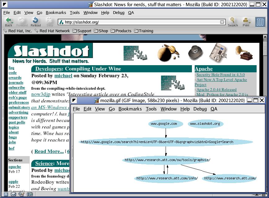
B  Screenshots

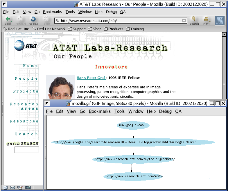
Figure 12: Prototype system screenshot 1
Figure 13: Prototype system screenshot 2

C  Bibliography

References

[1]
AT&T Research Labs , "The DOT Language", http://www.research.att.com/erg/graphviz/info/lang.html, February 2003.
[2]
AT&T Research Labs , "Welcome to GraphViz", http://graphviz.org/, February 2003.
[3]
Bergmann, S., "phpOpenTracker", http://www.phpopentracker.de/, February 2003.
[4]
Institute of Electrical and Electronics Engineers, "Hyperlinks", RFC 1866, Institute of Electrical and Electronic Engineers, 1998.
[5]
The Mozilla Organization, "Mozilla Hackers's Getting Started Guide", http://www.mozilla.org/hacking/coding-introduction", February 2003

Footnotes:

1SpiderGraph will not, under any circumstances, disclose this information to a third-party or its developers.


File translated from TEX by TTH, version 3.33.
On 2 Jun 2003, 21:44.